
Imprimir STL Tubarao RC 3D imprimivel gratuito em escala 1/8 (Shark.Aero) Modelo 3D - 2865167
Things 3D Fila
Tubarao RC 3D imprimivel gratuito em escala 1/8 (Shark.Aero)
Veículos R/C
Se você ainda não tem uma máquina para imprimir este arquivo pode comprar uma impressora 3d aqui!
Você pode imprimir este modelo 3d com estes filamentos ou com estas resinas 3D.
Sobre o objeto 3D Tubarao RC 3D imprimivel gratuito em escala 1/8 (Shark.Aero)
Este é um arquivo desenvolvido e projetado com ferramenta CAD.
Se você ainda não sabe criar seu próprio modelo 3D eu te ensino neste artigo tutorial sobre Tinkercad.
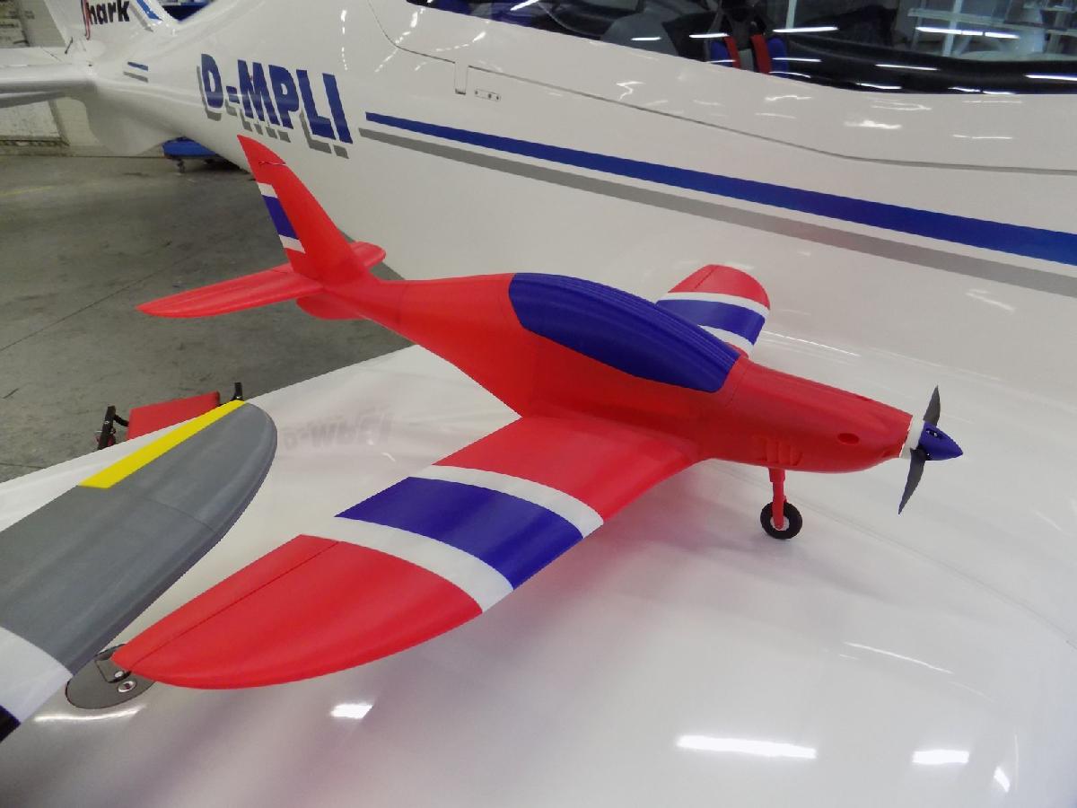
Tubarao RC 3D imprimivel gratuito em escala 1/8 (Shark.Aero) foi projetado para Impressora 3D. The airplane is a suitable model for experienced RC pilots as a transition model from EPP models to 3D printed. Thanks to the chosen airfoil, it flies slower and more gently compared to equally large 3D printed models currently available. With the recommended configuration we tested 10 minutes flight and it flies more briskly in the version without the landing gear.G-codes up to version 5.0 were generated using Cura 3.1.0, later Cura IMADE3D Edition 3.5.1 slicer (https://www.imade3d.com) which we recommend instead of the currently available version of UltiMaker Cura 5.2.2, or another. We achieve higher quality codes, especially with Z Seam alignment. Codes have been tested with Original Prusa MK3S+ printer. Recommended material is PLA 3D Fila, landing gear parts could be ABS, HIPS, PETG XT 3D Fila or other materials.News:• April 2023: added version with detachable wing and some improvements v6.3.Downloads:https://www.shark.aero/downloadshttps://www.thingiverse.com/SharkAeroYouTube Channel:https://www.youtube.com/channel/UC_mdViBBp7xAXUPLbK0KcDgBasic specifications:Wingspan: 990 mmLength: 856 mmWing area: 12.9 dm2Airfoil: Clark Y modifiedTake-off weight: ~940 g (according to spec.)Printed weight: ~540 g (according to material, printer and g-codes)Center of Gravity: beside the main landing gear legFlight time: 10 min.Recommended equipment:• Brushless motor: Turnigy 3530/14 1100KVhttps://hobbyking.com/en_us/turnigy-d3530-14-1100kv-brushless-outrunner-motor.html• Controller: 30A (must be thin, due to small space under the battery)https://hobbyking.com/en_us/aerostar-30a-electronic-speed-controller-with-2a-bec-2-4s.htmlhttps://hobbyking.com/en_us/turnigy-ae-30a-brushless-esc.html• Battery: Turnigy 2200mAh 3S 25C Lipo Packhttps://hobbyking.com/en_us/turnigy-2200mah-3s-25c-lipo-pack.html• Servos: standard 9g (4 x)https://hobbyking.com/en_us/turnigytm-tg9e-eco-micro-servo-1-5kg-0-10sec-9g.html• Front wheel: 40 mm diam.https://hobbyking.com/en_us/40mm-wheels-5pcs-bag.html• Main wheel: 45 mm diam.https://hobbyking.com/en_us/45mm-wheels-5pcs-bag.html• Propeller: 9x6 CCWhttps://hobbyking.com/en_us/apc-style-propeller-9x6-bone-ccw-1pc.htmlhttps://hobbyking.com/en_us/apc-style-propeller-9x6-grey-ccw-2pcs.html• Piano wire 1 mmhttps://hobbyking.com/en_us/36-piano-wire-039.html• CA hinge sheet:https://hobbyking.com/en_us/ca-hinge-sheet-180mmx140mmx0-3mm.html• 2 mm wire for wheel axes (alu, steel, carbon rod)(we tested a small piece of PLA 3D Fila filament - it broke during the first landing, maybe will be usable stronger material)• Cross recessed countersunk head screw 2.5x12 (5 pcs + 2 pcs for detachable wing)www.fabory.com/en/fasteners/screws/cross-recessed-countersunk-head-screw-for-chipboard-pozidriv-steel-zinc-plated-2-5x12mm/p/29240025012• Servo lead extention 15 cm (2 pcs)https://hobbyking.com/en_us/15cm-servo-lead-extention-futaba-26awg-10pcs-set.html• Straight wire 2F to 1M Y lead (optional)(it is not necessary if you have a 6-channel receiver and connected ailerons to separate channels)https://hobbyking.com/en_us/6cm-futaba-26awg-straight-wire-2f-to-1m-y-lead-5pcs.html• Linkage stoppers for 1 mm pushrods (optional)https://hobbyking.com/en_us/brass-linkage-stopper-for-1mm-pushrods-10pcs.html• Carbon fiber tube or rod Ø4 mm (2x51 mm + 1x35 mm, optional for carbon landing gear reinforcement)https://hobbyking.com/en_us/carbon-fiber-tube-hollow-4x750mm.html• Carbon fiber tube Ø8 mm (240+300 mm, optional for detachable wing)https://hobbyking.com/en_us/carbon-fiber-tube-hollow-8x750mm.htmlAssembling:Necessary equipment:CA glue, soldering iron, extra slim pliers, cutting pliers, cross screwdriver #1 and #2, scissors (small file, sandpaper, sharp blade).We do not recommend using OEM CA adhesives for example from HobbyKing.com, we had cases of detachment of parts and control surfaces. We use and recommend Soudal Cyanofix 84A or Loctite adhesive.Fuselage:Used parts:• fuselage_1~4• gill_L, R• canopy_glass (front, middle, rear)• 7 pinsIf you are using the version with the detachable wing, in part no. 2, drill holes Ø8 in the marked places. Be careful, the material is fragile. First, pre-drill holes Ø3-4 mm. With a soldering iron open the large hole in the fuselage below the canopy.Use a carbon tube Ø8, length 300 mm as the front tube. Pull the tube through the fuselage in a slow circular motion, constantly checking the correct position. Do not use brute force.Use length 240 mm as the rear tube. The tubes do not need to be glued - they will be reusable.Stick all parts of the fuselage together. Use pins to connect, will allow for more precise assembly. The brim of the pins can be cut with scissors. Don't forget to stick the gills.Separately stick together all canopy parts.Note: To remove the canopy from the fuselage, you can use a flat screwdriver. Push the screwdriver into the gap near the lock and turn.Wing:Used parts:• wing_L_1~3• wing_R_1~3With a soldering iron open the marked cable holes in the root ribs of the centerplane and first glue both root wing parts. Then glue all other parts of the wing.Tail:Used parts:• stabilizer_L• stabilizer_R• fin• rudder• rudder_horn• rudder_hinge• 2 pinsGlue the pins into one half of the stabilizer, then glue both parts of the stabilizer together. Stick the stabilizer into the profile cutout at the end of the fuselage, hinges must be up. Put the upper rudder hinge on the upper rudder pin, glue the hinge into the groove on the fin. The rudder must move freely. Stick the rudder horn with the rudder and the fin with the fuselage.Control surfaces:Used parts:• aileron_L• aileron_R• elevator_L• elevator_R• hinge sheet• a 2 mm wide spacerCut 8 pieces of hinges 5 x 15 mm from the hinge sheet and glue into ailerons and elevators. Place a 2 mm wide spacing between the elevator hinges and both elevators glue into the stabilizer in zero position. The gap between the elevator and the stabilizer must be 1 mm. Glue ailerons into the wing, the gap is also 1 mm.Main landing gear:Used parts (2 pieces of each):• main_gear_leg• main_gear_lever_leg• main_gear_spring• 45 mm wheel• wheel axesIf you are using the version with carbon reinforcement, insert Ø4, 51 mm long carbon tubes or rods into the legs - no need to glue. Glue the legs into the wing. The legs must be rotated in the right direction and glued in the entire case. Stick the main gear spring with the lever leg. Install the wheel and secure it with glue at the ends of the axle. Hang the wheel with spring on the main gear leg, use ~0.8 mm wire as the axis. Insert the end of the spring into the wing - the spring remains non-glued, will be an exchangeable part.Front landing gear:Used parts:• front_gear_bracket• front_gear_leg• front_gear_tube• font_gear_spring• front_gear_lever• 40 mm wheel• wheel axisFirst test whether the leg and spring rotate freely in the tubular part of the gear, if not, use sandpaper or print a wider „front_gear_tube“ part - we usually print the 10.3 – 10.5 mm version for a vertical printed leg. Stick both parts together. The tube part stick to bracket with glue around the perimeter - partial sticking may cause breakage. If you are using the version with carbon reinforcement, insert Ø4, 35 mm long carbon tube or rod into the leg - no need to glue. Insert the leg into the tube and at the other end attach the lever perpendicular to the direction of flight. During sticking, check the ability to rotate the leg. Install the wheel and secure it with glue at the ends of the axle.With a soldering iron open the hole in the front of the fuselage and try to insert the assembled front gear.Install the RC equipment:If you haven't done so yet, with a soldering iron open the large hole in the fuselage below the canopy. Now you are ready to install the RC equipment.
Não deixe de imprimir e compartilhar este modelo 3d. Não deixe sua impressora 3D parada. Mas se você não tem uma impressora 3D ainda, escolha a sua agora.