Imprimir STL Robo Drone Andarilho com Corpo Balancante #5 versao direcionavel Modelo 3D - 3102186
Things 3D Fila
Robo Drone Andarilho com Corpo Balancante #5 versao direcionavel
Robótica
Se você ainda não tem uma máquina para imprimir este arquivo pode comprar uma impressora 3d aqui!
Você pode imprimir este modelo 3d com estes filamentos ou com estas resinas 3D.
Sobre o objeto 3D Robo Drone Andarilho com Corpo Balancante #5 versao direcionavel
Este é um arquivo desenvolvido e projetado com ferramenta CAD.
Se você ainda não sabe criar seu próprio modelo 3D eu te ensino neste artigo tutorial sobre Tinkercad.
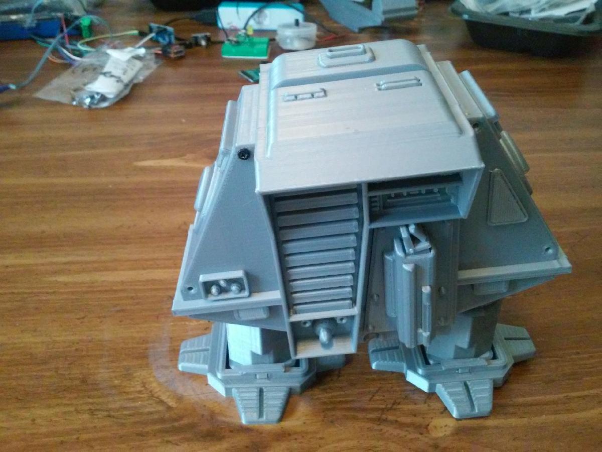
Robo Drone Andarilho com Corpo Balancante #5 versao direcionavel foi projetado para Impressora 3D. This is my remix of Robothuts "Rocking Body Walking Robot Drone #5". I built his original design and several others he's posted to Thingiverse. His original design is a pin walker driven by one motor/gearbox. It walks in a straight line when you turn it on. I decided to build a remote controlled steerable version. It has two N20 gearmotors driven by a L9110S dual H bridge. An Arduino Pro Mini controls the motors with feedback from a cam and switch on each leg. The Arduino uses the feedback to keep the motors in sync. The Arduino receives commands from an IR remote through a TSOP4838. The IRLIB2 Arduino library is used to decode the 12 bit Sony codes. The universal remote is set for a Sony VCR. Power is provided by the guts of a 2600 MAH power bank. The 18650 cell has solder tabs which is important to make everything fit in the robot. The charge board in the power bank also boosts the cells voltage to 5 Volts. It works well even it 's a little slow. The motors are rated at 30 RPM at 6 Volts.The drone/robot was printed on an Ender2 and a FolgerTech 2020.The 3D printed parts needed from RobotHuts design are:footclip 2latch 1bodyBack 1 / the door will be replacedfoot 2leg 2bodyFront 1The motor frame and body frame are the 2 big parts that need replacing. The rest of the parts are clamps, mounts, and cams. The 2 cams are marked left and right. The tilt cam goes on the right side and is keyed. The battery clamp is what the charge board is mounted to with hot glue. The switch mounts are the stepped plates that the switches are mounted to. You need 2 of them. The switch mount is then mounted to the motor clamp with screws and nuts, and adjusted using the slots. There are a left and right motor clamp. The V on the motor clamp points to the front of the robot. The leg pins are a different length than robotHuts original design and you need 2. The arduino mount and mtr_drv_clamp are stacked with the L9110S and Arduino and screwd to the lower holes in the motor frame. The video should provide enough details if anyone should want to build one. The wiring is pretty simple so I haven't included a schematic. The Arduino source code includes the pin connections between the Arduino, ML9110S, TSOP4838, and switches. The common of each switch goes to ground and the N.O. terminals go to the Arduino input pins. I used a piece of strip board to make a power distribution bus. This is where the power pins of the boards and sensors are soldered. The Arduino program uses the IRLIB2 library. I can't remember for sure how I installed the library but I think I followed these instructions:https://learn.adafruit.com/using-an-infrared-library/hardware-neededYou may need to use the Decoding IR data section of that page to get the codes your remote is sending. You can edit my Arduino program for your particular codes. I set my universal remote to a Sony VCR. It outputs 12 bit sony codes. I've commented out a lot of serial debugging lines that can be uncommented if needed.The program has a switch debounce routine that was necessary for it to work at all.The '#define BIT_DEBOUNCE_COUNT 8' at the top defines how many times the switch state has to remain unchanged before the switch state is updated. It uses shift registers to keep track of the bit trains from the switches.This is not an easy build. Finding the right size screws seems to take a lot of time. Most of the screws used are 2mm X 12mm self tapping or 3mm X 12mm machine screws. Some had to be cut shorter. The power switch I used is smaller than the holes in RobutHut's design. I slotted the holes in the switch to make it fit. A larger switch would probably interfere with the internal moving parts anyway. There is not much room inside for the electronics. I had to modify body frame using the stl RobotHut posted. Fusion 360 is not very good at this and neither am I. In the importing and reduction of the stl, some of the detail seems to have gotten lost. There is one artifact visible on the print. It is a faint triangle on the side of the body. I spent a lot of time trying to clean up the body after converting it from the mesh. I used 3D builder to fix the non manifold errors but Prusa Slic3r says 2 remain. All the slicers I tried will still slice the model correctly.My video:https://www.youtube.com/watch?v=a80CQ_oQmnAParts I used:roller switch:https://www.banggood.com/5Pcs-AC-125V-1A-Mini-SPDT-Micro-Switch-Long-Hinge-Roller-p-998613.htmlslide switch:https://www.banggood.com/10Pcs-Black-Mini-Size-SPDT-Slide-Switches-On-Off-100V-2A-DIY-Material-p-1011746.htmlArduino Pro Mini:https://www.banggood.com/3Pcs-ATMEGA328-328p-5V-16MHz-Arduino-Compatible-Nano-Size-Module-Board-p-1006451.htmlTSOP4838 IR receiver:https://www.banggood.com/5Pcs-IR-Receiver-Infrared-Radiation-Module-38KHz-TSOP4838-DIP-3-p-945168.htmlUpdate:I built an Attiny based IR remote for the robot:https://www.thingiverse.com/thing:3566978I replaced the Arduino program on this page with the same program on that page. It still works with a universal remote. The program also has some bug fixes.
Não deixe de imprimir e compartilhar este modelo 3d. Não deixe sua impressora 3D parada. Mas se você não tem uma impressora 3D ainda, escolha a sua agora.