Imprimir STL Parte de calibracao de compensacao de largura combinada e tamanho horizontal Modelo 3D - 1747770
Things 3D Fila
Parte de calibracao de compensacao de largura combinada e tamanho horizontal
Testes de impressão 3D
Se você ainda não tem uma máquina para imprimir este arquivo pode comprar uma impressora 3d aqui!
Você pode imprimir este modelo 3d com estes filamentos ou com estas resinas 3D.
Sobre o objeto 3D Parte de calibracao de compensacao de largura combinada e tamanho horizontal
Este é um arquivo desenvolvido e projetado com ferramenta CAD.
Se você ainda não sabe criar seu próprio modelo 3D eu te ensino neste artigo tutorial sobre Tinkercad.
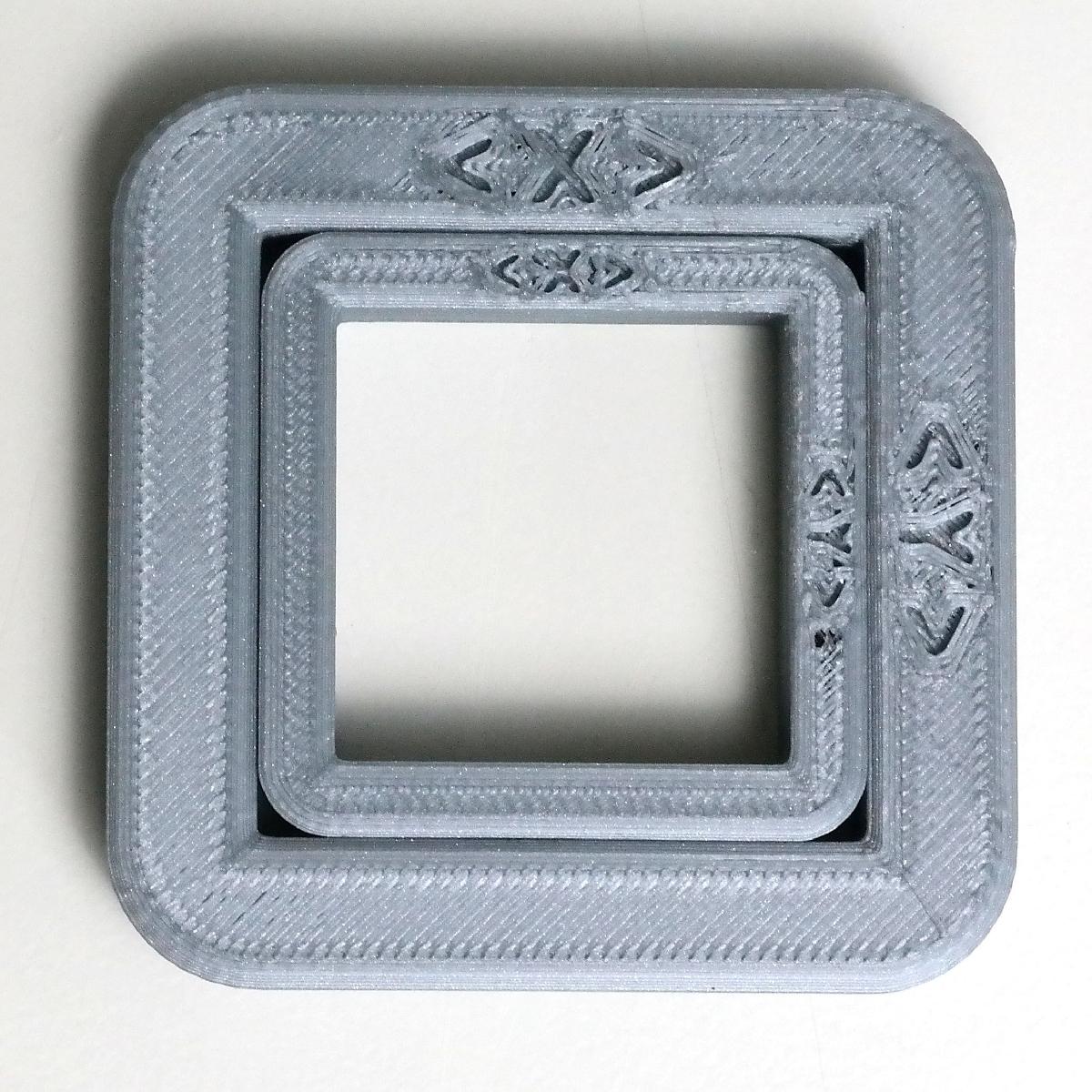
Parte de calibracao de compensacao de largura combinada e tamanho horizontal foi projetado para Impressora 3D. A common problem with using the well-known calibration cube of arbitrary size to calibrate x/y scaling (e.g. stepper steps per mm for cartesian printers) is it omits any increase of width due to the FDM extrusion process (talking about those small ripples at the edge of your part).Other calibration parts suggest to reduce your flow rate to adjust wall thickness, but this is a VERY bad idea, as this (lengthty) explanation shows: http://forums.reprap.org/read.php?1,704450To exactly calibrate for A) x and y scaling and B) horizontal size compensation or exact wall thickness, this thing here should help you:Print Part1.stl (the bigger part) and measure inner dimension (ID) and outer dimensions (OD) on both the x and y axis.Then for both axes seperately:Your new scaling factor (e.g. steps per mm) is: Old scaling factor * ( 100 mm / (ID + OD) )Your walls are printed to thick by: (20 mm + ID - OD) / 2.To reduce wall thickness use appropriate tools, such as the "horizontal size compensation" Simplify3D offers in the "Others" tab. In Cura the according setting is called "horizontal expansion" in the "Walls" section. The value to put there is (OD - ID -20 mm) / 4.After putting in all compensations, print both Part1.stl and Part2. stl. They should fit each other quite nicely* (you gotta push a bit, but not crazy). If they don't fit yet, further increase wall thickness compensation a bit and/or switch over to "outside to inside" wall ordering.Hope that helps, have fun!/* Why and how does it work? More thorough explanation compiled by msamblanet:100/(ID+OD) provides a linear scale factor to compensate for the part being overall under or oversized - 100 is the desired size and ID+OD is the actual so dividing these gives you the correction factor. This can be used to adjust your steps-per-mm OR to scale the part in your slicer (which would have the same effect).(OD-ID-20)/4 is calculating the error in each bar of the part - (OD-ID) is the total width of both bars...each bar has a desired size of 10mm...so the -20 removes the 20mm desired size and we are left with just the error. As each bar has 2 walls, dividing by 4 gives you how far off each individual wall is. This would then be plugged into the XY compensation in the slicer to tweak the walls slightly to correct the wall thickness.The small differences can be difficult to read on calipers. If you need more accuracy, you could scale the print and then scale the 100 and 20 in the equations by the same amount...Also keep in mind that pushing molten plastic through a nozzle is not the most precise science so don't expect machining perfection.
Não deixe de imprimir e compartilhar este modelo 3d. Não deixe sua impressora 3D parada. Mas se você não tem uma impressora 3D ainda, escolha a sua agora.