
Imprimir STL Contador para Wilder Winder Modelo 3D - 4264438
Things 3D Fila
Contador para Wilder Winder
Passatempo
Se você ainda não tem uma máquina para imprimir este arquivo pode comprar uma impressora 3d aqui!
Você pode imprimir este modelo 3d com estes filamentos ou com estas resinas 3D.
Sobre o objeto 3D Contador para Wilder Winder
Este é um arquivo desenvolvido e projetado com ferramenta CAD.
Se você ainda não sabe criar seu próprio modelo 3D eu te ensino neste artigo tutorial sobre Tinkercad.
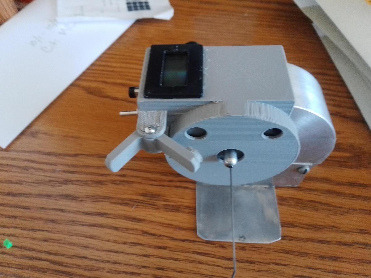
Contador para Wilder Winder foi projetado para Impressora 3D. A printed counter for the Wilder Winder for rubber-powered indoor planes. The electronics are based on a Trumeter 7000AS, a high speed counter that can keep up with the output shaft, so it displays true turns on the rubber. Up and down counting, and reset.I made one prototype, so it may take some fiddling and adjustment.NEW V2: This version replaced the spring loaded mechanical brake with a magnetic brake. This provides more reliable braking, and is easier to install.Notes:This build provides an output-shaft counter for the Wilder Winder. It uses a reed switch and magnet as input to a high speed counter. It fits the stock output shaft fitting. It also provides a brake/lock that has 1-turn positioning.Print as follows:Wheel flat face downLever, lay on its side, as an "L". Some printers may need support in the magnet hole, but try withoutCase, place top face (where counter mounts) down. Add supports in the area of the brake lever hinge, but try without supports elsewhere.The following parts are needed:Counter: Trumeter 7000AS counter, https://www.galco.com/buy/Trumeter/7000ASGPS 14A reed switch, https://www.amazon.com/gp/product/B07WQVLRQC(2) 6mm diameter rare earth magnet, https://www.amazon.com/gp/product/B07CVPC3YJPushbutton switch for reset, momentary, 7mmm mounting hole, https://www.amazon.com/gp/product/B0816MRKSJMini toggle switch for reversing, SPST, 6mm mounting hole, https://www.amazon.com/gp/product/B01M3261RLBattery holder for CR2032, such as https://www.amazon.com/Shapenty-Plastic-Vertical-Battery-Sockets/dp/B071F3HW8J. Note: I did not use this, but did not like what I usedA small spring (lightweight compression spring, 1cm ID). I used something from my garage. You may be able to wind something from 0.015" wire. Should not be strong, used to release the brake. Mine had about 6-7 turns of 0.015" wire, 1cm ID.10k-ohm resistor10nF capacitor (#103)Scrap wire and heat shrink insulation6-32 x 1.25" Stainless Steel Pan Head machine screw (from Ace Hardware). MUST BE SS, cannot be ferrous.(2) #2 buttonhead wood/sheet metal screws, 1/4" long (or cut down)Shoe Goo or Goop glueMedium CAAssembly:Trial fit the wheel on the collar of the rubber hook assembly. You will need to remove the screw that holds it to the shaft. Ream the hole in the wheel if neededGlue a magnet in one recess of the wheel with Shoe Goo. Cut a piece of lead scrap, from a wheel weight or otherwise, and balance the wheel. I just balance on some thin wire, say 1/16", and add lead until it seems close. Pound flat, fit into recess, and glue in.Build the electronics. The reed switch goes in the recess in the case. The end nearer the center of the shaft needs to be soldered to some wire, wrapped in shrink wrap, and placed in the channel to route it away from the winder and to pin 4 of the counter. The other end gets the 10k resistor, and routs to pin 3. I don’t recall, I may have had the resistor in the first end in the channel and shrink tubing. Whatever fits. Resistor goes to pin 3. Capacitor goes across pins 3 and 4. Resistor and cap form debounce circuit.Reset button goes pin 1 to pin 4Direction switch goes pin 2 to pin 4. "On" is count down, off is count up.I soldered one lead to pin 4, then brought all the needed wires together to that lead, rather than introducing too much heat at the counter.Install the counter, switches, and wires, and rout away from the winder case.Remove the upper right screw from the Wilder Winder. This will be replaced with the SS screw.Install the wheel into the case, and feed rubber hook collar into the hub of the wheel. Carefully align the opening in the wheel hub with the opening in the collar. Be sure it is aligned with the unthreaded side of the collar. Best to have a tight fit so things stay aligned.Install the case onto the wilder winder, carefully guiding the collar onto the shaft without loosing alignment. Make sure the shaft hole is pointing downward, also the hub hole, so that you can see it. Insert the screw. This is a pain, use long needle nose. Its a pain. Worth repeating. Magnetic screwdriver REALLY helps!Rotate the wheel unto the cutout aligns with the mounting screw hole. Insert the mounting screw and snug down. Be sure everything clears. I had to lightly grind the top of the screw to avoid the wheel, but in the end it was because the recess for the screw had flashing in it.Place the second rare earth magnet on the outside of the face of the round part of the case, near the hole for the brake, and rotate the wheel until it grabs the magnet. If it repels, flip the magnet. Once the magnet is stuck to the magnet in the wheel (through the plastic case), mark the exposed side of the magnet.*Using Shoe Goo, or CA, glue the magnet, marked side in, into the locking lever. Let it set up.Using the two small screws, mount the locking lever in the hinge area. Be sure it rotates freely, and the magnet land goes into the case hole cleanly.Test operationNote: initially mine did not work. After experimentation, I found that the magnet, while hitting near the center of the reed switch, was not causing reliable closure. It was more reliable with the magnet further out, so I made a new larger wheel (thus the cutout for the mounting screw). If you have trouble, you may need to move the reed switch inward a bit. You may want to assemble without glue initially to see how things work out.Operation: Wind, and be sure counter agrees with the mechanical counter. Switch the toggle to count downward. Touch button to rest. When you stop, press the brake button in gently, and unwind slightly until it catches. It should do so in less than 1/4 turn of the output shaft. The brake will release with slight forward motion on the crank. Be sure you have a good grip on the rubber, the brake will likely release as you remove the rubber.
Não deixe de imprimir e compartilhar este modelo 3d. Não deixe sua impressora 3D parada. Mas se você não tem uma impressora 3D ainda, escolha a sua agora.