Imprimir STL cobertura de wafer LED COB de 50 watts Modelo 3D - 4117348
Things 3D Fila
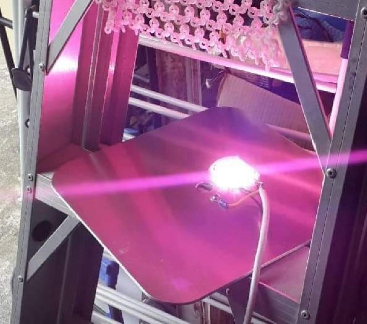
cobertura de wafer LED COB de 50 watts
Decoração
Se você ainda não tem uma máquina para imprimir este arquivo pode comprar uma impressora 3d aqui!
Você pode imprimir este modelo 3d com estes filamentos ou com estas resinas 3D.
Sobre o objeto 3D cobertura de wafer LED COB de 50 watts
Este é um arquivo desenvolvido e projetado com ferramenta CAD.
Se você ainda não sabe criar seu próprio modelo 3D eu te ensino neste artigo tutorial sobre Tinkercad.
cobertura de wafer LED COB de 50 watts foi projetado para Impressora 3D. https://www.aliexpress.com/item/32982350492.html?spm=a2g0s.9042311.0.0.52274c4dIAhxfqThese COB LED units have direct mains input.My cover is designed to protect against electric shock by covering the live electrical parts.Be certain to solder carefully(I solder before attaching), run wires straight out and lay as flat as possible. I've seen some shocking soldering by people over the years. Here's my guidelines:"Tin" the solder pads quickly with solder, you will see the surface change as the solder melts, you want to leave a shiny blob that is a nice smooth bump tapering down to the edges of the pad.Strip no more than 4mm from the end of the Line and Nutral conductors, twist, apply solder between the iron and the copper, moving the solder to melt into the wetted out area of the twisted strands as it heats. Recheck you have no more then 4mm tinned, trim if necessary. There should still be a thin film of flux on the soldered strands.Holding the cable straight and approx 30mm from the end, lay it on top and melt it into the blob on the COB LED. "L" is brown, "N" is blue in international wiring code for mains. Once the solder blobs fully merge, remove the iron while holding the wire absolutely still. if the wires are cooking your fingers you are too slow in your soldering technique, keep holding the wire straight and blow on the joint.Fixing the COB: You need a BIG heatsink. Use the 3D cover as a drilling guide. Do an extra hole close by for earth wire WHICH MUST BE SECURELY ELECTRICALLY CONNECTED.Use 12mm M3 screws or longer, push up through the heatsink, fit the COB with thermal paste over the screws and nut it tightly. Then push the 3D cover over the top and nut it on also. Note that you must nut the COB directly to the heatsink, not with the cover, overheating would soften the cover and lift the COB allowing more overheat.Be sure to secure the mains cable to the heatsink so that strain does not wear at the connections.Paint the heatsink black for better radiation cooling.The second file has a little more of a pocket for the nuts so that the cover pushes back closer to the heatsink.
Não deixe de imprimir e compartilhar este modelo 3d. Não deixe sua impressora 3D parada. Mas se você não tem uma impressora 3D ainda, escolha a sua agora.