
Imprimir STL Dobradica Parametrica Modelo 3D - 2187167
Things 3D Fila
Dobradica Parametrica
parts
Se você ainda não tem uma máquina para imprimir este arquivo pode comprar uma impressora 3d aqui!
Você pode imprimir este modelo 3d com estes filamentos ou com estas resinas 3D.
Sobre o objeto 3D Dobradica Parametrica
Este é um arquivo desenvolvido e projetado com ferramenta CAD.
Se você ainda não sabe criar seu próprio modelo 3D eu te ensino neste artigo tutorial sobre Tinkercad.
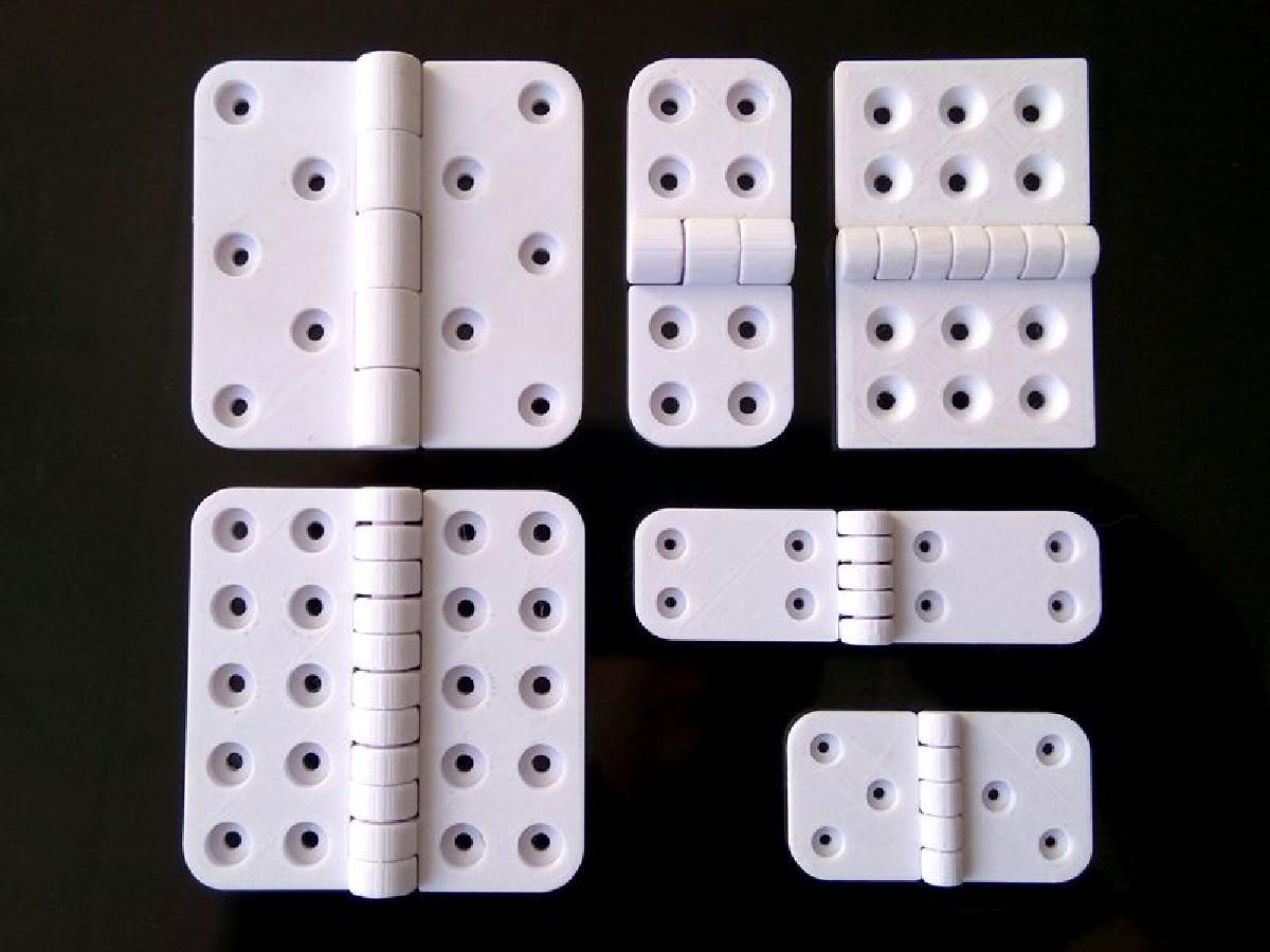
Dobradica Parametrica foi projetado para Impressora 3D. Parametric Butt HingeThis is a parametric butt hinge designed in OpenSCAD, offering a wide range of parameters for customization. The hinge is designed to be printed in one step, but the individual leaves can be printed independently if desired. And in the case of applications that require an external pin, the default fused pin may be disabled, to leave a pin shaft ready to accept an external pin, during post printing assembly.Note:In the event that the Thingiverse Customizer is not working, which happens from time to time, you can still open and edit SCAD files directly in an SCAD editor, like OpenSCAD.Experimental Version:An experimental version of this model may be found here, https://www.thingiverse.com/thing:2351153The experimental version includes additional features that are still being developed, or would otherwise over complicate the base model. I have made the experimental version available for those who would like to brave early access to some of the features that will possibly find there way into the base model, eventually. Please note, the experimental version is not updated as often as the base model, and may still include bugs and untested configurations. Parameter OverviewAssembly OptionsMale Leaf EnabledPrint the male leaf if true, otherwise omit it from the print.Female Leaf EnabledPrint the female leaf if true, otherwise omit it from the print.Leaf Fillet EnabledEnable filleted leaf corners. Aside from aesthetic value, filleted corners can help with warping to a degree.Pin EnabledBy default, the hinge is designed to be printed in one go, with a hinge pin fused to the female leaf. However, there may be applications where one may prefer to use an external pin. For instance, in the case where a metal pin is preferred for the sake of strength. In applications where an external pin is to be used, the pin may be omitted from the female leaf, by setting "Pin Enabled" to false. Pin Auto Size EnabledIf true, this will set the pin diameter to the leaf gauge.If false, the pin diameter may be specified by the "Pin Diameter" parameter.Pin Shaft Counterbore EnabledCut a counterbore into the end caps of the knuckle joints if true.While the pin shaft counterbore may be added even when the internal fused pin is enabled, the primary purpose of the pin shaft counterbore is to allow what ever external pin or bolt is being used in the case of an external pin, to be set flush with the top and bottom edges of the hinge, in the case where the internal pin is disabled, i.e. "Pin Enabled" is false.Fasteners EnabledInclude fastener holes if true.If false, leave the leaves free of fastener holes.Knuckle Gusset TypeSelect whether or not to use knuckle gussets, and if so what type. Knuckle gussets add strength to the transition between the knuckles and the leaves. The length of the knuckle gussets is equal to the fastener margin size, so that the gussets will never overlap any fastener holes.There are four styles of knuckle gusset to choose from.None: No knuckle gussets.Linear: Straight edge gusset projected from a tangent on the knuckle down to the fastener margin on the leaf.Circular: Basically a simple fillet, tangential to both the knuckle cylinder and the surface of the leaf.Parabolic: A vertex form parabola, tangential to the knuckle cylinder, with its turning point tangential to the surface of the leaf at the fastener margin.Throw AngleThe angle of the hinge joint. The hinge joint range is from +180 degrees fully closed, to -90 degrees fully opened. The default throw angle is 0 degrees, ie. opened flat.This can be used either for assembly analysis, or in the case where one wishes to print the hinge standing vertically, it can be used to set a partially closed angle to keep the hinge stable during printing. For vertical printing, an angle of 120 degrees should keep the hinge stable during printing.If you just want to print the hinge flat on the build plate, then keep the throw angle at 0 degrees for your printable model.Flip ModelRotate the model 180 degrees about the z-axis. This is useful for viewing the top and bottom pin shaft counterbore parameters. ResolutionThe geometric model resolution. Corresponds to the number of sides used to construct cylindrical parts of the model, like the knuckle joint segments, and the leaf fillets.For example, a "Resolution" of 8, would specify cylindrical component elements to be constructed from 8 sides. a "Resolution" of 32 would result in 32 sided cylindrical component elements, and so forth.For a smooth model, a "Resolution" of 64 and above is recommended. By default "Resolution" is set to 128.Component ColorThis is used purely to color the model in the Thingiverse Customizer. It should not affect the color of the model, printed from a color printer.Hinge Parameters:Hinge WidthThe width in millimeters, of the entire hinge, from the outer edge of the left leaf, to the outer edge of the right leaf.Leaf HeightThe height in millimeters, of the hinge along the knuckle joint axis.Leaf GaugeDefines the thickness in millimeters, of the leaves and the radius of the knuckle joint.Component ClearanceThe inter-component gap in millimeters.Recommended values range from 0.3mm for a tight fit, to 0.5mm for easy-er manipulation after printing. Clearance values of 0.3 or below can be challenging to print. I have succeeded in printing a few of these hinges with component clearances of 0.2mm and 0.25mm. However, quite often, sub 0.3mm clearance results in a locked up knuckle joint, where the leaves break before the hinge loosens up. A clearance of 0.4 or greater should release without to much trouble.Note: The more knuckle segments there are, the greater the initial joint friction strait off the build plate. So for higher knuckle counts (7 or greater), component clearances of 0.4 or higher, may be required.If the knuckle joint is not moving free at 0.4mm or higher, try re-printing slower at a higher resolution, in particular z resolution. Lower temperatures can help as well.For PLA 3D Fila, a resolution of x=0.3, y=0.3, and z=0.15, at a speed of 6mm/s or less, with temperature 190 degrees C, seems to support a component clearances of 0.3mm to 0.4mm relatively well.All of the sample STL files in the "Thing Files" section, are set to 0.3mm component clearance.Knuckle CountThe number of knuckle segments in the knuckle joint.This number should be an odd number.For most applications, a knuckle count of 3 or 5 should suffice. However, higher knuckle counts can offer increases in strength relative to gauge size and hinge dimensions.Pin DiameterManually specified pin diameter. This value is only used by the model, if "Pin Auto Size Enabled" is set to false.If "Pin Auto Size Enabled" is true, then the pin diameter is automatically set to the leaf gauge size.Pin Shaft Counterbore Parameters:(Top or Bottom) Pin Shaft Counterbore DiameterThe diameter of the pin shaft counterbore. The counterbore is only added if "Pin Shaft Counterbore Enabled" is set to YES.(Top or Bottom) Pin Shaft Counterbore DepthThe depth of the pin shaft counterbore cut. The counterbore is only added if "Pin Shaft Counterbore Enabled" is set to YES.(Top or Bottom) Pin Shaft Counterbore ShapeThe shape of the pin shaft counterbore hole. Currently circular, square and hexagonal are supported. In the case of square and hexagonal, the parameter "Pin Shaft Counterbore Diameter", refers to the diameter of a circle inscribed inside the square of hexagon.For the square shaped counterbore, this means that the diameter of the counterbore is equal to the size of the sides of the square.For the hexagon, the counterbore diameter is equal to the perpendicular distance between any two parallel sides of the hexagon.The counterbore is only added if "Pin Shaft Counterbore Enabled" is set to YES.Fastener Hole Parameters:Fastener Head TypeCan be set to either counterbore for pan head machine screws, or countersunk for flat countersunk screws.The chamfer angle for flat countersunk may be adjusted by varying the other fastener hole parameters. For instance, a thread diameter of 3mm (e.g. M3 machine screws), a head diameter of 9mm, and a countersink depth of 3mm, with give a chamfer angle of 45 degrees.Counter Sink DepthThe depth below the surface of the leaves to sink the fastener heads.For M3 machine screws 2.5 to 2.6 is usually enough.If the fastener holes are not countersunk, then there will be mechanical interference between the fastener heads the the opposing leaves when the hinge is closed.Fastener Thread DiameterThe diameter of the threaded portion of the fastener hole.This can be made smaller than the fastener thread in order to support self tapping screws, or larger to give machine screws enough room to pass through.Fastener Head DiameterThe diameter of the counter sunk head portion of the fastener hole.Usually a good idea to make this diameter 0.5mm to 1.0mm larger than the actual fastener head diameter. For M3 machine screws, which typically have 6mm diameter pan heads, an "Fastener Head Diameter" of 7mm works well.Fastener CountThe number of fastener holes per leaf. The total number of fastener holes in the entire hinge will be "2 x Fastener Count".Fastener holes are arranged in one or two columns along the height of the hinge, as specified by "Fastener Column Count". Fastener Column CountSpecify whether to arrange the fastener holes on a leaf, in one or two columns.Fastener MarginThe distance from the circumference of the fastener head, to the edge of the leaf.Values between 3mm and 5mm are recommended for small to medium gauge hinges.
**Modelo 3D para Impressão 3D: Análise do "Dobradica Paramétrica do Bumbum"**### Introdução
O avanço da tecnologia de impressão 3D tem possibilitado a criação de uma vasta gama de produtos e ferramentas personalizáveis. Entre esses produtos, a "Dobradica Paramétrica do Bumbum" se destaca como uma solução inovadora projetada para atender a diversas necessidades de montagem, ajustando-se a diferentes especificações através de parâmetros amplamente personalizáveis. Este modelo foi desenvolvido utilizando OpenSCAD, uma linguagem de programação popular para a modelagem 3D e design paramétrico. Neste texto, exploraremos em detalhes as funcionalidades, aplicações e considerações relativas à impressibilidade do modelo, além de oferecer um guia prático para a utilização de suas variáveis.
### Descrição do Modelo
A "Dobradica Paramétrica do Bumbum" é um modelo de dobradiça projetado para ser impresso em uma única etapa. Contudo, permite que suas folhas (partes móveis) sejam impressas separadamente, se desejado. Isso é especialmente útil em aplicações que exigem personalizações específicas ou que se beneficiariam do uso de um pino externo, o que pode ser realizado desativando o pino fundido padrão. O modelo é um exemplo ideal de como a impressão 3D pode oferecer soluções ad hoc em engenharia e design, permitindo que os usuários modifiquem as características do objeto para atender suas necessidades específicas.
### Personalização Através de Parâmetros
O grande diferencial da "Dobradica Paramétrica do Bumbum" é a possibilidade de personalização através de parâmetros ajustáveis. Abaixo, vamos discutir os principais grupos de parâmetros disponíveis no modelo.
#### Opções de Montagem
- **Folha Masculina e Feminina**: Permite ao usuário decidir se deseja incluir uma ou ambas as folhas da dobradiça durante a impressão. Essa possibilidade é útil para economizar material em situações onde apenas uma folha é necessária.
- **Pino e Ajustes**: O modelo permite a escolha entre um pino de dobradiça fundido ou um pino externo, o que é essencial para adaptar a resistência e funcionalidade da dobradiça em diferentes aplicações. A opção de ajustar o diâmetro do pino também é uma vantagem significativa, pois permite a adequação a diferentes medidas de materiais.
- **Fixadores e Contrafuros**: Os usuários podem optar por incluir furos de fixação, adequando o modelo para melhor integração em projetos maiores. Além disso, a configuração de contrafuros para os eixos de pinos dá flexibilidade nas montagens que requerem um acabamento mais limpo e estético.
#### Parâmetros de Dobradiça
Os parâmetros como largura, altura, e espessura das folhas, sabendo que cada um deles impacta diretamente na robustez e movimento da dobradiça, são cruciais. Por exemplo:
- **Largura da Dobradiça**: A largura pode ser ajustada conforme a necessidade do projeto em que a dobradiça será utilizada, permitindo uma maior versatilidade.
- **Altura e Calibre da Folha**: Estas métricas afetam diretamente a estrutura do modelo. Um modelo mais alto pode proporcionar um movimento mais amplo, enquanto o calibre determinará a resistência da dobradiça.
### Aplicações Práticas
A "Dobradica Paramétrica do Bumbum" possui uma vasta gama de aplicações práticas. Ela pode ser utilizada em:
- **Móveis**: Em armários, portas e outros móveis que se beneficiam de dobradiças ajustáveis. A capacidade de improvisar e alterar medidas garante que esta dobradiça pode ser utilizada em diversas construções de móveis.
- **Projetos de Engenharia**: Profissionais que trabalham em protótipos de engenharia podem se beneficiar da simplicidade e eficiência deste modelo na montagem.
- **Artesanato e DIY**: Com a possibilidade de personalização rápida, esse modelo pode ser perfeito para criadores e entusiastas do "faça você mesmo" que procuram soluções rápidas para suas criações.
### Considerações na Impressão 3D
A impressão 3D da "Dobradica Paramétrica do Bumbum" exige atenção a vários aspectos técnicos:
- **Resolução da Impressão**: A recomendação de uma resolução de 64 ou superior garante um produto final mais suave. Isso se traduziará em melhor funcionalidade ao permitir um movimento mais fluido entre as folhas da dobradiça.
- **Folga nos Componentes**: Os parâmetros de folga são cruciais para garantir que a dobradiça funcione corretamente após a impressão. Valores em torno de 0.3 a 0.4 mm proporcionam um bom equilíbrio entre ajuste apertado e facilidade de montagem.
- **Temperatura e Velocidade de Impressão**: As condições recomendadas de temperatura e velocidade são igualmente importantes. A sugestão de temperatura ao redor de 190 graus Celsius e velocidade de impressão de 6 mm/s ou menos é uma boa prática para garantir que as peças se solidifiquem corretamente e mantenham as dimensões necessárias.
### Conclusão
A "Dobradica Paramétrica do Bumbum" é um modelo de dobradiça inovador que exemplifica o potencial da personalização no design 3D. Projetada para ser prática e versátil, este modelo se adapta a diferentes necessidades de montagens e aplicações, tornando-a uma excelente escolha para profissionais e entusiastas. Através das suas opções de personalização extensivas, o modelo não só se destaca em funcionalidade, mas também promove a criatividade em projetos de impressão 3D.
### Referências
Embora não haja referências externas diretas em um texto como este, os conceitos e práticas discutidos são amplamente reconhecidos na comunidade de impressão 3D e podem ser encontrados em recursos de design 3D e fóruns de discussão. Para mais informações sobre o modelo, vale a pena visitar a página do "Dobradica Paramétrica do Bumbum" no Thingiverse e consultar a documentação associada, bem como as atualizações sobre versões experimentais que estão em desenvolvimento.
Dessa forma, a "Dobradica Paramétrica do Bumbum" se torna não apenas uma ferramenta útil, mas também um exemplo de como a impressão 3D pode revolucionar os processos de design, fabricação e personalização de produtos.
Não deixe de imprimir e compartilhar este modelo 3d. Não deixe sua impressora 3D parada. Mas se você não tem uma impressora 3D ainda, escolha a sua agora.